Ljubljana ATLAS group is involved in design and production of online radiation monitor for ATLAS detector. The purpose of the radiation monitor is to provide online information about the radiation dose at various locations in the ATLAS detector. It will measure total ionizing dose (TID) and non ionizing energy loss (NIEL) and, in the inner detector, it will monitor degradation of current gain in the DMILL bipolar transistors which will give also information about their exposure to thermal neutrons.
The radiation monitor must measure doses in ranges from Gy to hundreds of kGy and from 1011 n/cm2 to 1014 n/cm2 of 1 MeV neutrons NIEL equivalent in Si. RADFETs with different oxide thicknesses will be used for TID measurements. 1 MeV equivalent neutron fluence will be determined using different types of pin diodes either from measurement of forward bias at given forward current (1 mA) or from measurement of leakage current in the reverse biased diode.
More details about radiation monitor can be found in Conceptual Design and Functional Specifications of ATLAS Radiation Monitor, and in documents listed in the documents folder.
System working!
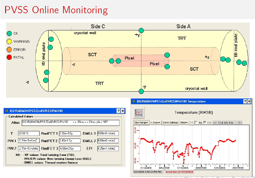
The system has been fully installed in 2008 and is taking data. There are monitors at 14 locations in the Inner detector and at 48 locations in rest of ATLAS. In Fig 1. below various windows from user interface of radmon readout software are shown. Green circles show the 14 monitoring locations in the Inner Detector. By clicking on them readouts of sensors at this location can be seen at any time. Sensors are read out periodically every hour or so. The results are stored in the database and the history of read-out values is also available.
Fig 1: windows from user interface of radmon readout software
The main part of the on-line radiation monitor is the Radiation Monitor Sensor Board (RMSB). On this board radiation sensors and a temperature sensor are mounted. There are two types of RMSBs in ATLAS of which one is be used in the Inner Detector and the other on other measurement locations. Requirements for the monitor in the inner detector are very demanding because it must cover largest range of doses and because of very limited possibility for access for eventual interventions. Therefore, RMSBs in the inner detector host a number of radiation detectors which cover the large range of doses and provide a high level of redundancy. Because of very uncertain temperature conditions at some locations in the inner detector (could vary between -20 and +20oC) the RMSBs are made of ceramics and are equipped with a heater which enables us to keep the board at constant temperature few degrees above 20oC.
On the photo below one can see a prototype of the Inner Detector RMSB. The outer dimension of the housing box for the ID is 40x40x8 mm3.
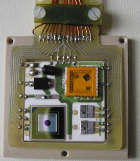
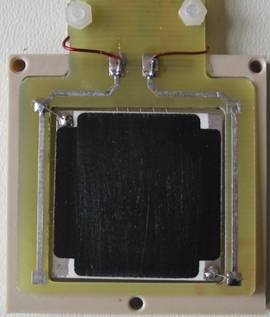
Fig 2.: Left: top side of the populated ID hybrid connected to a PCB frame in the bottom part of PEEK housing. The hybrid is populated with radfet package containing 3 radfets, CMRP diode, BPW34F diode, epitaxial Si diode, two DMILL test structures and a temperature sensor. Right: back side of the hybrid showing the resistive heater.
For locations in the rest of ATLAS the RMSBs are simple PCBs with dimensions of 3 x 4cm2, hosting high sensitive pin diode (CMRP), a temperature sensor (10 kOhm NTC) and ceramic package containgn one thick oxide radfet. A RMSB is therefore be connected with 4 wires: one for each sensor + return wire.
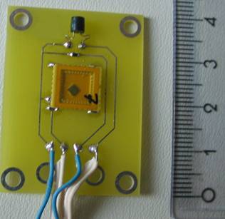
Fig 3.: RMSB for rest of ATLAS locations.
The RMSBs are read out using standard ATLAS electronics. Sensors are read out using ADCs on ELMB boards which communicate with ATLAS DCS over the CAN bus. Current pulses for biasing of sensors, which can be converted to voltage via resistors, are provided by ELMB DAC boards which plug into ELMB boards. ELMB-DAC board (shown in the Fig 4. below) has 16 channels.
For the inner detector one DAC board serves one RMSB whereas for the rest of ATLAS up to 6 RMSBs are connected to one DAC board.
Each Inner Detector RMSB needs 13 ADC channels. Rest of ATLAS RMSB needs 4 ELMB ADC channels (2 for sensors, 1 for current monitoring and 1 for temperature).
Fig 4.: Photo of the ELMB-DAC board (taken from ELMB-DAC users manual www.nikhef.nl/pub/departments/ct/po/html/ELMB/DAC10.pdf Dimensions of the board are 65x72 mm2 .
Fig 5. Scheme of connections of 4 RMSBs to ELMB and ELMB-DAC. Cables between RMSB and patch panel can be long. For Inner Detector monitors 15 m long cables were tested. Rest of ATLAS monitors worked over 200 m long cables.